#
EQ with personal measurements (***)
Up to this point, EQ was used with measurements provided in different databases, and while some of them are available with the 5128∆ project that allows for cross database comparisons, unit variation is still a very big factor that should be addressed, especially if an IEM and/or brand are known for having mediocre quality control. To remedy this problem as well as a few others, personal measurements should be used. There are three ways in which measuring your own set can help when using EQ.
For the rest of this section, it is assumed that the measurement rig is an IEC-60318-4 compliant occluded ear simulator, aka a 711 coupler, and that all measurements of an IEM are done with the same ear tips unless stated otherwise.
Before measuring
If possible, listen to the IEMs before doing any measurements as they can introduce biases and placebo. The measurement rig is much more sensitive than human hearing, and so not all "errors" will be audible, unless of course you do measurements first and fool yourself into hearing a problem where there aren't any.
#
Unit variation
Personal measurements are useful for determining whether or not a particular unit of an IEM is faulty or not. Not only that, it also serves as a useful indicator that some part of the IEM might require cleaning or fixing. For example, clogged filters, or debris in vents can drastically change the sound of an IEM, even if it measured fine out of the box.
Unit variation issues
- While measurements between different measurement rigs shouldn't be compared, it is useful in this case for identifying large deviations indicative of quality control issues or flaws in the IEM
- IEMs with large unit variation should also be checked quickly for potential distortion issues
- For brands with a history of silent revisions, measurements are necessary
- Any failure due to use and fatigue, like filters getting clogged, can change the FR
Unit variation is usually not a major issue, but when it is, it can be confusing when trying to EQ. If a unit has significant variation that is not easily fixable through EQ (eg having a substantial drop/boost in the bass region), then it is better to simply return it rather than salvage it. These differences will be perceived by the listener, but even with seemingly large deviations in measurements, human hearing is not as sensitive and can be easily fooled by different biases.
The following image shows three different samples of the same IEM. Unit variation can manifest itself as either poor QC, revisions, or pre-production units. The differences shown are relatively significant, and are located in a region that seems to be polarizing considering how the correct final version has the least energy there.
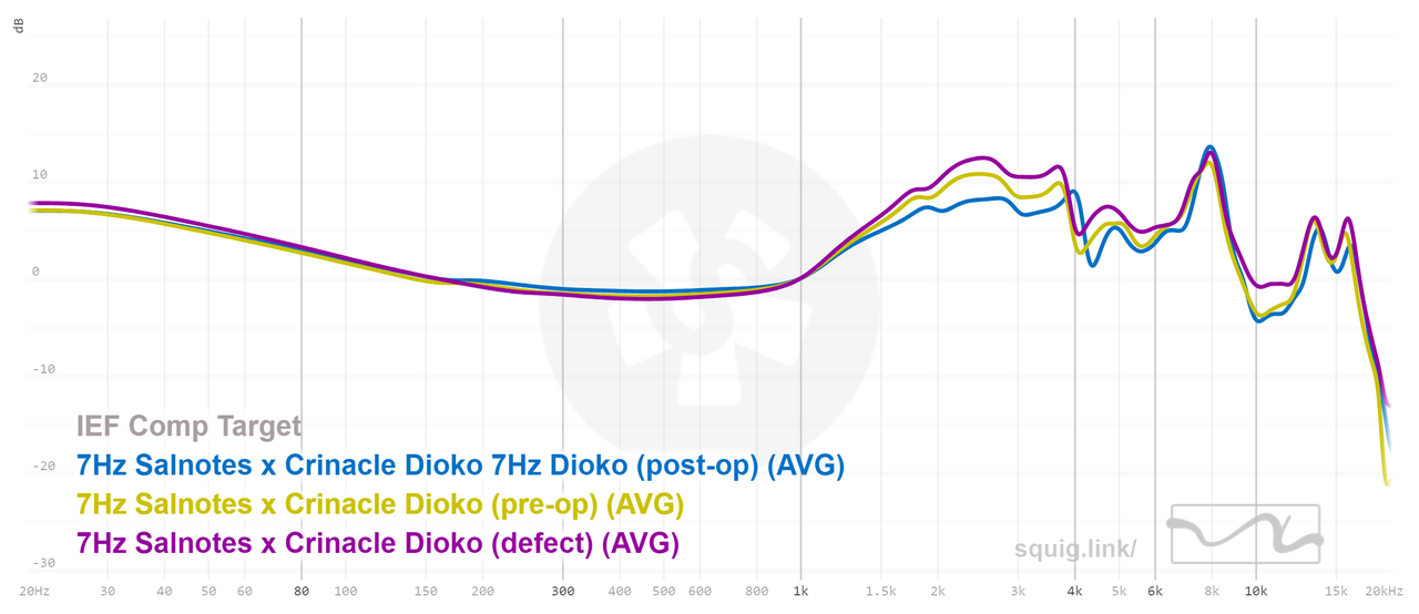
The next one shows an example of an IEM that has somehow passed the manufacturers quality control stage. Notice how low in amplitude the whole range below 1 kHz is on the defective model; this large discrepancy would require filters with very high gain, and subsequently high preamp negative gain. Not ideal, and not worth using EQ to fix it.

For your own measurements, check to see if there are significant deviations, and if there are, simply EQ the unit to the desired FR following the guide. Re-measure your unit with EQ applied to see if the deviations have actually been removed and listen for any possible (albeit very rare) signs of distortion or other artefacts.
#
Channel Matching
Depending on quality control, some IEMs and individual units can have significant channel imbalances. Depending on the frequency range being affected and the volume difference, the imbalance can be audible: for most manufacturers, a deviation of 1dB is generally considered as acceptable. Fixing these imbalances relies on the same steps and ideas as previous sections, but requires separate and independent channel EQ.
Measuring channel matching
- Calibrate the coupler and ensure that there are no audio modifications (eg EQ)
- Measure one side of the IEM, taking note of how deep it was inserted and of the volume at which it was measured at
- Measure the other side, making sure that the volume and the insertion depth is the same (ie have the same resonance peak frequency)
- If needed, re-measure any side if there is a leak, a mismatched resonance peak, or error in volume
If both sides have been measured to have the same resonance peak location and the same loudness, then comparisons and conclusions can be made between the two sides. The same rules as before apply here.
Fixing channel imbalances
- Before even attempting to EQ, listen to the IEMs and determine if there is any discernible differences between channels. This step should optimally be done before measuring the IEMs as this can introduce bias and placebo
- If there are differences, listen and try to identify the regions where they are situated. Music should be avoided in favor of pink noise and/or sine sweeps
- The measurement should then be used with relation to what was heard
- Any deviation below 1dB and/or around the resonance frequency should be ignored
- Use necessary filters to fix the imbalances while constantly comparing with pink noise and/or sine sweeps
- If there is a consistent difference throughout the whole frequency range, use a channel specific preamp or limiter to adjust volume on one side
The image shows two IEM units, for which both their channels have been measured. For the Hola, this particular unit displays a consistent difference of around 1dB between channels; whether this is audible or not has to be determined through listening tests. If there's a need for correction, a simple preamp (or peak/shelf filter for focusing on a frequency range) can be used. The G10 also has slight differences, but because they are so narrow, they will most likely not be noticeable.

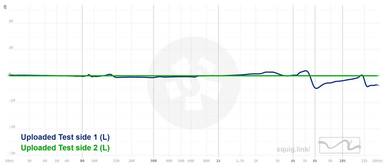
The following images shows an IEM for which there is a channel imbalance in the ear gain region. At first glance, the small peaks are not only different in level, but also not aligned between the two sides. Fixing this with the left image isn't so straightforward; the second image, with side 1 being compensated to side 2 offers a better look at what the differences are, and how to fix them.

IEM or hearing?
It is important to note that while channel imbalances covered so far only refer to those caused by the IEMs themselves, your hearing can also be responsible. High frequency roll-off is particularly frequent as age progresses, and slight sealing issues can also cause differences in bass. It's why listening tests are always recommended and why measurements might not be enough to cover all bases. If imbalances occurs consistently in the same regions, it is safe to assume they are hearing related. For hearing-related imbalances, use a tone generator and sine sweeps, and use EQ until perceived sound is centered (ie sounds like mono).
#
Insertion depth and ear tips
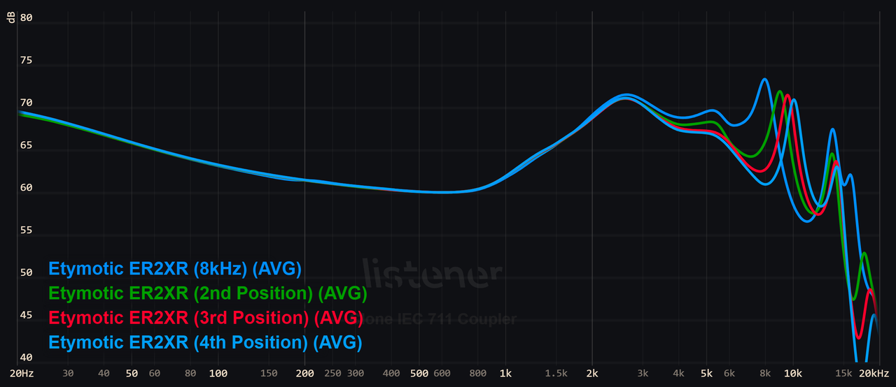
Insertion depth changes not only the frequency of the canal resonance peak, but also affects the surrounding frequency ranges, and oftentimes significantly. While previously established rules state that measurements shouldn't be scrutinized above 10kHz, there is still some use in looking at insertion depth profiles of an IEM in order to not only see how it reacts to different coupling scenarios, but also to find a match for your own personal experience.
A tube resonance is created when IEMs seal the canal/coupler, and changes in frequency (6kHz - 12kHz) depending on insertion depth. Commonly referred to as canal resonance, or length mode, they should only be modified based on listening tests, and not through graphs.
The following image is an extreme example of how insertion depth can affect FR. As the insertion depth changes, so do the surrounding frequencies' levels. Depending on the IEM's shape, intended insertion depth, and the ear tips being used, insertion depth location can shift drastically; not only that, there can also be damping, from the ear canal and/or IEM in that region, which can affect both the amplitude and Q of the resonance peak. It is therefore useful to have insertion depth profile done through your own measurement rig.
Another effect of insertion depth is a slight increase in amplitude below the driver's resonant frequency, as shown below. Combined with the change in treble, insertion depth is an important factor to consider when using EQ.
The following images shows possible FR changes attributable to ear tips. Ear tips usually influence the bass region because of seal, and treble because of insertion depth as well as other reasons outside the scope of this guide. Assuming proper seal, the bass factor can be ignored, leaving only the treble as being an affected factor. Depending on the shape and size of the ear tip, the resonance peak frequency can shift considerably. The image however does show changes despite them having the same resonance peak frequency; while it is usually recommended not to scrutinize measurements past 10kHz, it is an interesting thing to note that ear tips can change upper treble response, usually in the form of damping.

Rules based on insertion depth changes and ear tips
- Assuming the location of the canal resonance peak has already been found, measurement at said location should be obtained for the IEM that will be recipient to the EQ
- Measurements should be done with the same ear tips that will be used for actual listening
- Check if the resonance peak is audible: if so, follow previous steps for fixing treble peaks
- Experiment with different insertion depth in case treble is not up to preference
#
Filters
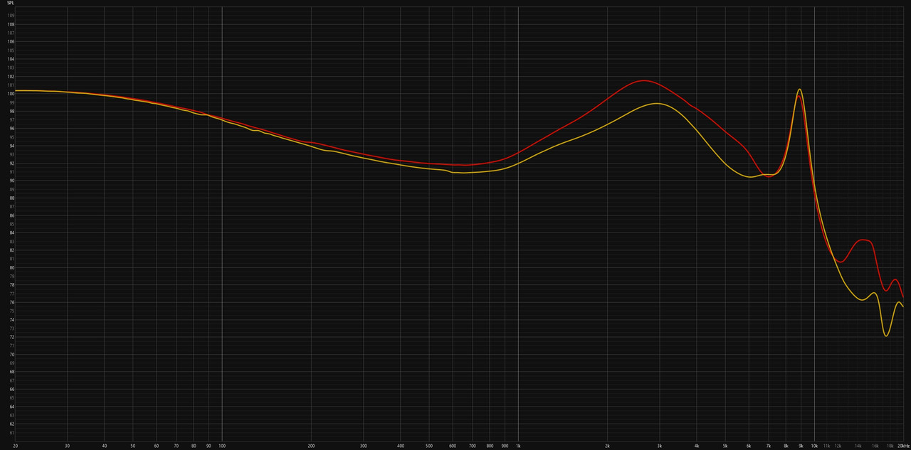
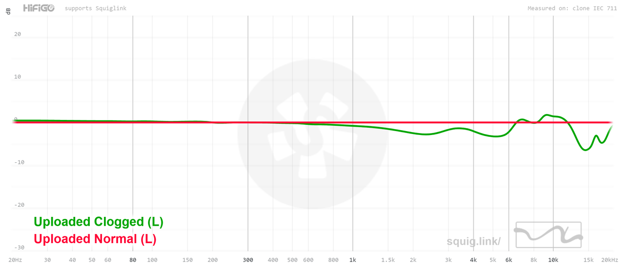
Many IEMs use small filters/dampers that usually cover the nozzle and/or tubes out of the nozzle. While some are acoustically transparent, many dampen high frequency response to various degrees depending on the filter acoustic resistance (in many cases denoted as density). With time, these filters can become clogged, resulting in either wide band volume reduction, or narrow band volume reduction. The latter is of note here: as a filter gets clogged, the acoustic resistance changes, and manifests itself as further damping.
The image below showcases the effect of partial filter clogging, where a relatively wide drop centered at 2.5 kHz and another smaller drop at 5.5 kHz can be observed. The behavior of clogged filters with regards to "clog level" and cleaning is not consistent, and therefore IEMs with potential clogging issues should be measured to assess the change in FR and necessary corrections.
It is important to note that clogging can occur even if the filter looks clean and unimpeded by debris.